In short: Discover how an automatic vehicle barrier system works, from access authorization to sensors and safe closing, including RFID and ANPR/LPR integration.
Quick answer: An automatic vehicle barrier system controls access through a motorized barrier and an authorization system. It first receives a request — for example, from a remote control, an RFID card, a QR code, or a license plate recognition camera — then validates the permission and sends a command to the controller. The arm rises to allow passage and lowers again once the vehicle has crossed and the area is clear, in line with the configured safety logic. Actual operation depends on the model, the sensors, the software, and the installation.
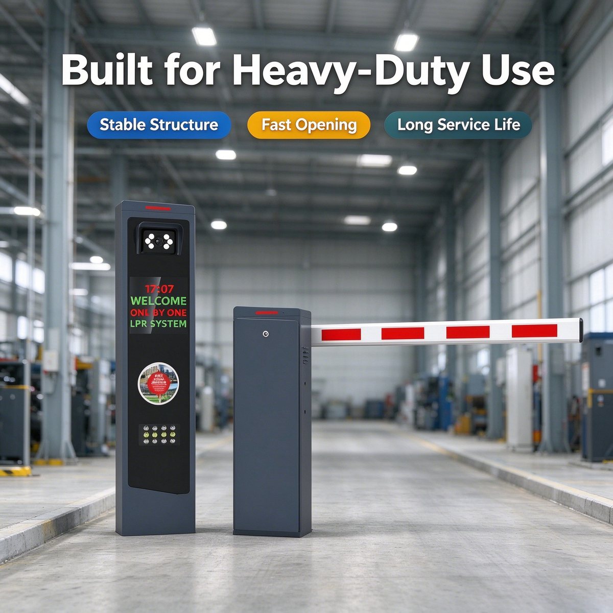
A basic system usually includes the barrier housing, the motor and drive mechanism, the arm, the control board, the device that requests opening, and compatible safety elements. Depending on the project, an RFID/UHF reader, an ANPR/LPR camera, a vehicle detector, a radar sensor, a ticket system, or management software may be added.
Not every access point needs the same combination. A visitor parking lot may require tickets or QR codes, while a resident entrance may use RFID, and an industrial access point may combine plate identification, credentials, and procedures for freight vehicles.
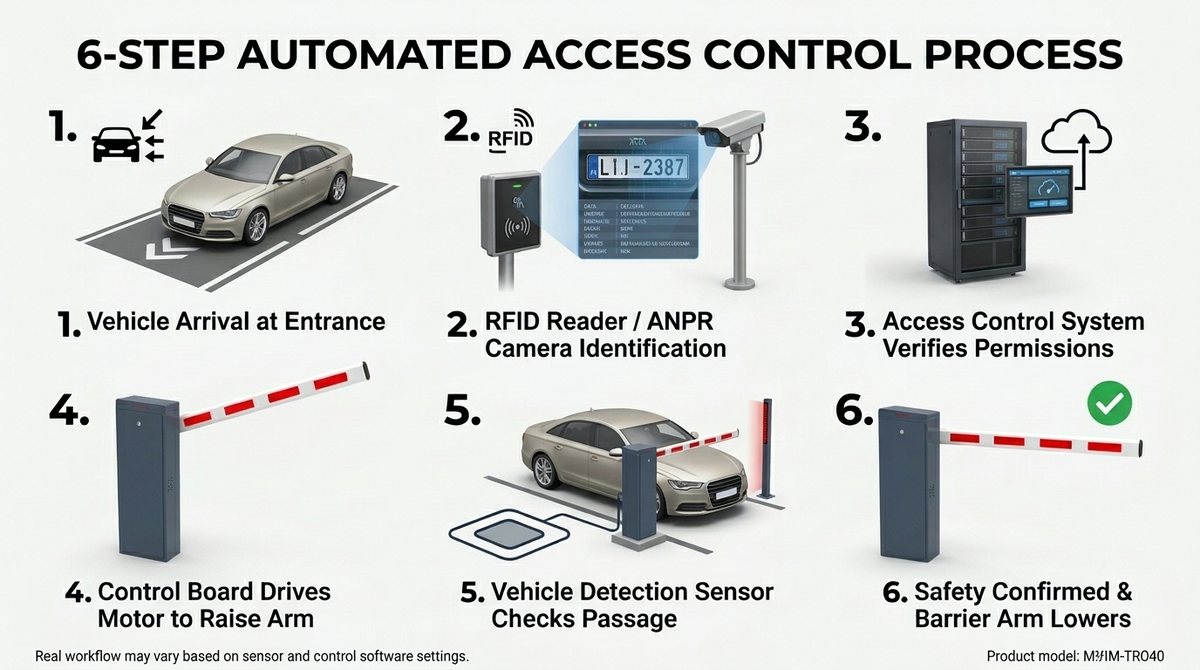
The driver approaches the lane and uses the method intended for the site. They may present a card, scan a code, use a remote control, or wait for a camera to read the plate. The signal must be received within the operating conditions defined for the system.
The controller or the access platform verifies the request according to the configured rules. With RFID, a registered credential can be checked; with ANPR/LPR, the recognized plate can be compared against an authorized list or the software rules. Identification should not be confused with authorization: recognizing a plate does not automatically mean the vehicle has permission to enter.
When the system confirms a valid authorization, it sends a signal to the barrier controller. The connection can be made through a compatible interface, such as a dry contact, Wiegand, or a network connection, depending on the equipment. Before integrating third-party products, the compatibility of the interfaces and the software must be confirmed.
The motor and the drive mechanism move the arm to the open position. The movement time depends on the model, the length and type of arm, and the operating settings. To compare equipment, use the datasheet for the specific model and do not extrapolate a figure from a short arm to a long one.
Vehicle detectors, induction loops, radar sensors, or compatible photocells can help identify the presence of a vehicle and protect the movement area. The selection, placement, and configuration of these devices must respond to the geometry of the lane and the risks of the site. No sensor should be considered a safety guarantee without proper installation and testing.
Once the vehicle has crossed and the detection signals indicate that the closing area is free, the system starts lowering according to the configured logic. The installer must test the full cycle with different vehicle sizes and positions, and document how the system responds to an anomalous sensor signal.
When the barrier is connected to a management platform, the system can log events such as authorized entries, plate reads, times, or alerts. The available data depends on the camera, the controller, the software, and the configured retention rules. Define who can consult the records and how long they will be kept.
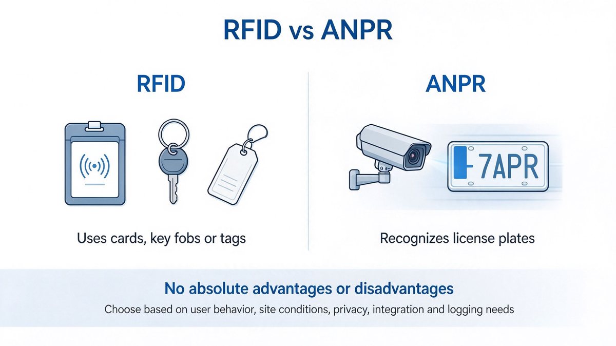
An RFID or UHF reader detects a compatible card or tag and sends the information to the controller or the management system. If the credential is authorized, the system issues the opening command. The read range depends on the reader, the tag, the antenna location, and the environment, so it must be tested under actual installation conditions.
An ANPR/LPR camera captures the plate and the recognition engine converts the image into text. The software compares the result against the access rules and, when appropriate, sends a signal to the barrier. Performance can vary with lighting, angle, vehicle speed, plate dirt, and environmental conditions, so testing during both day and night is advisable.
If the project requires an existing parking system, confirm which interfaces and protocols each component supports. Check the complete flow: reading or identification, validation, opening command, vehicle detection, closing, and event logging. An integration is not considered complete until error cases and operational exceptions have also been tested.
The response to a failure depends on the model and the accessories installed. Some configurations may support manual release, a backup battery, or a UPS; these options must be confirmed in the product datasheet and defined during design. It should not be assumed that all equipment includes electrical backup or that all of it adopts the same fail-safe position.
Before putting the system into service, establish a procedure for power loss, network loss, reader failure, plate recognition error, and emergency activation. Operating personnel must know how to stop use of the lane, request assistance, and apply the approved procedure without exposing themselves to the movement of the arm.
Start with the lane width, the clear height, the vehicle volume per hour, and the cycle frequency. Determine whether the access point requires a straight arm, a folding arm, or another compatible type, and confirm the appropriate length based on the lane, the wind, and the obstacles. The goal is to select a system for the actual conditions, not solely by price or advertised speed.
Verify the power supply for the exact model. For Mexican installations, ask whether the quoted version supports 127 V / 60 Hz and request the corresponding datasheet. The electrical connection, grounding, and protections must be reviewed according to site conditions and by qualified personnel.
Evaluate exposure to rain, dust, heat, humidity, and wind. Request the environmental specifications declared for the model and check whether the housing, the arm, and the accessories are suitable for the installation location. At industrial or outdoor access points, record these conditions in the quotation request.
Finally, define the authorization method, the safety devices, the software integration, technical support in Spanish, the warranty, and spare parts availability. Ask that the proposal clearly state what is included and what must be supplied separately.
The BAROXON Mexico site presents categories for vehicle barriers, high-speed barriers, ANPR/LPR systems, automatic RFID barriers, radar sensors, and vehicle detectors, as well as accessories and spare parts. These categories allow different access control configurations to be evaluated, but the correct combination must be defined based on the project requirements and the compatibility of the specific model.
For a technical proposal, share the lane width, the expected flow, the vehicle types, the authorization method, the available power supply, and the environmental conditions. Ask that the quotation identify the barrier model, the arm type and length, the sensors, the interfaces, the accessories, and the commissioning services.
Not necessarily. The system must verify that the recognized plate meets the authorization rules. If the plate is not registered, the read is unclear, or the software cannot validate access, the system must follow the procedure configured for those cases.
The need for a sensor and the type required depend on the safety design, the features of the model, and the conditions of the access point. Detection devices must be selected, installed, and tested in accordance with the manufacturer's instructions and the risks of the site.
It may be possible if the interfaces, protocols, and software are compatible. Before buying, request technical confirmation and test the complete flow under real conditions, including error scenarios and manual procedures.
Confirm the supply supported by the exact model and ask about the 127 V / 60 Hz version where applicable. Do not rely solely on the general description of a category: review the datasheet for the unit that will be supplied.
Test authorization, opening and closing, vehicle detection, safety functions, failure modes, software integration, and event logging where applicable. Document the results and train the personnel who will operate the access point.
An automatic vehicle barrier system combines a motorized mechanism with access authorization and detection devices. For it to work correctly, each stage — identification, validation, opening, detection, closing, and failure response — must be designed and tested as part of a whole. In Mexico, it is advisable to confirm the power supply, the environmental conditions, the interfaces, and the support before selecting the equipment.


